Geometric Format for the Giza Complex
1 Linear and angular dimensions for the three large pyramids at
Giza, Egypt.
(Calculated by Sir W. Flinders Petrie)
2 Linear distances to each pyramid.
(Calculated by Sir W Flinders Petrie and confirmed by J. H. Cole)
3 New format and dimensions for the Giza complex.
(The site coordinates are rotated to accommodate the south side of Khufu’s pyramid. This represents Earth’s possible east-west orientation during construction.)
4 Linear alignment involving the three pyramids.
(Basic geometric analysis indicates the misalignment of the three
pyramids at Giza)
5 Linear alignment, including a circular pyramid format.
(Closer investigation reveals the intended geometry required to align
the three pyramids)
6 Extended circular and triangular development, utilizing the complex.
(A “mirror” image of the pyramid complex indicates advanced knowledge in geometry)
7 The third circle and the 2:1 ratio revealed.
(Three large circles are related to each other mathematically. Two
circles demonstrate the identical ratio equal to the two large pyramids)
8 Relationship to the “Sphinx”, “valley temples” and, “boat pits”.
9 The “mirror” image for the complete complex with Earth’s angular tilt, and the number pi revealed.
10 Conclusion.
11 References
1. Linear and
angular dimensions for the three large pyramids at Giza, Egypt.
Sir William Matthew Flinders Petrie
(1852-1942), a man who devoted most of his mature life in search for the truth;
a man who had no former education in the field of Egyptology, became the first
Egyptological Chair in Britain.
Single-handed, this gentleman created a new
approach to Egyptian archeology by dissecting archeological sites in a
scientific and systematic manner. His tools for measure were calibrated to the
most accurate standard. The linear measuring instruments used were based on the
English inch, and meticulously he divided each into decimal format.
His measures have been challenged on several
occasions, however in 1925 AD his calculations were confirmed to be true within
one inch, when the Egyptian Government Survey Department appointed J. H. Cole
to perform this confirming survey.
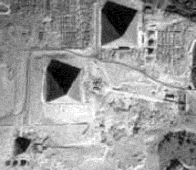
There are three large pyramids at the Giza
site, and to eliminate confusion, the largest (Khufu’s Pyramid) is referred to
as P1, followed by the center and almost equal in height being P2, leaving the
third and smallest pyramid noted as P3.
Petrie encountered difficulty while
measuring the north end and west side of P3, resulting in neither a true length
of measure for the north side, or the azimuth with reference to the west side.
To accommodate, the average measure has been applied (bracketed) to complete
the dimensions for this pyramid (Chart 1 and Ill. 1).
From Petrie, the length measures and
individual azimuth for each pyramid are as follows:
|
P1 |
Length |
Azimuth |
||||
|
North |
9069.4 |
-3'
20" |
||||
|
East |
9067.7 |
-3'
57" |
||||
|
South |
9069.5 |
-3'
41" |
||||
|
West |
9068.6 |
-3'
54" |
||||
|
|
|
|
||||
|
P2 |
Length |
Azimuth |
||||
|
North |
8471.9 |
-5'
31" |
||||
|
East |
8475.2 |
-6'
13" |
||||
|
South |
8476.9 |
-5'
40" |
||||
|
West |
8475.5 |
-4'
21" |
||||
|
|
|
|
||||
|
P3 |
Length |
Azimuth |
||||
|
North |
-4153.6 |
+16'
48" |
||||
|
East |
4149.2 |
+12'
23" |
||||
|
South |
4157.8 |
+12'
57" |
||||
|
West |
4153.9 |
(+14’
03”) |
||||
|
|
(inches) |
|
||||
|
|
|
|
|||
Chart 1.
Sir William Petrie’s measures for the three
large pyramids at Giza, Egypt
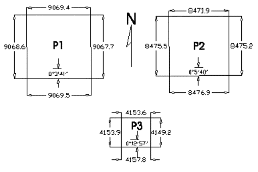
Illustration 1.
Sir William Petrie’s measures for the three
pyramids on the Giza Plateau, Egypt.
2.
Linear
distances to each pyramid:
Not excluding the works by J. H. Cole and
the Egyptian Survey Department, the following measures indicate the center
location for these three large pyramids on site.
North -
South East – West
Center of P1 to center of P2 13932 13166
Center of P2 to center of P3 15170 9450
Center of P1 to center of P3 29102 22616
(Converted to
English inches)
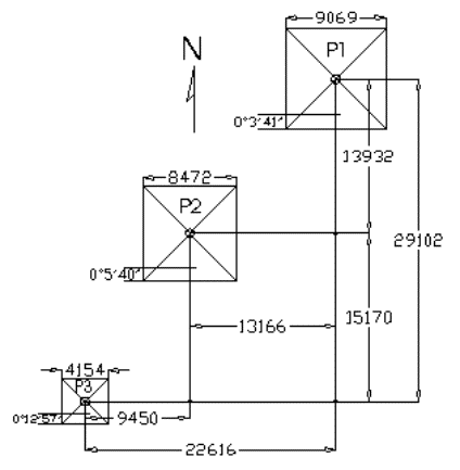
Illustration 2.J. H. Cole confirmed Petrie’s
measures for the pyramids, with reference to each other.
3. New format and dimensions for the Giza complex:
From the above illustrations, the minor
discrepancies in azimuth measure are most evident. However, when viewing P3
compared to P1 and P2, its four sides are drastically misaligned with our true
celestial coordinates. This issue prompted an investigation into analyzing the
possibility that the builders may have constructed the smaller pyramid further
from the true north-south axis with intent.
Before construction commenced, the
foundation for P3 required little preparation; an observation noted by Petrie
while surveying this structure. P3 is positioned in the most ideal area within
the complex, yet the larger foundations for both P1 and P2 involved extensive
engineering skills to prepare.
The two extremely large and complex pyramids
are built directing us closer to true north than the smaller pyramid. Did the
designers misalign P3 for us to consider viewing the pyramid complex
“regardless” of our present measure for true north, and only compare their
distances to each other?
Since we cannot verify Earth’s axial motion
over the past 5,000 years, we cannot assume that the ancient Egyptians built
the pyramids “offset” from true north. If we consider Earth’s present true
north direction “irrelevant”, then a new survey position can be selected with
reference to any given side from the three pyramids. The issue to be resolved
is; what side do we choose as the reference?
Although true north can be calculated from
celestial observations, it requires full knowledge of Earth’s daily orbital
position with respect to the Sun and the stars being observed. There is a far
simpler procedure to measure Earth’s axis utilizing the Sun’s rays. The Sun
rises from the east then sets in the west, and the ancient Egyptians built
obelisks for observing the shadows cast by these monoliths. It is this basic
and ancient monitoring technique for the Sun’s observed motion that prompted
this writer to implement the east-west coordinate for the south side of P1; it
“possibly” being the designers true reference line.
Using computer aided drafting, the complete
site is rotated showing the south side of P1 aligned with east to west (Ill.
3).
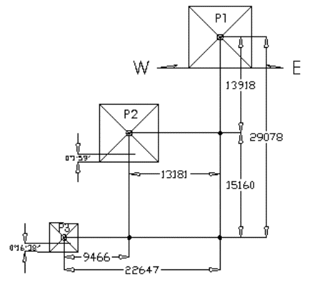
Illustration 3
A new dimension format is created by
choosing the south side of P1 to represent the designer’s true reference line
for Earth’s east-west axis.
4. Linear alignment involving the
three pyramids.
The debate continues, whether the pyramids
are built in a haphazard fashion, or geometrically aligned. However, a straight
line, marked L1, appears to eliminate any alignment possibility (Ill. 4).
The single and closest alignment, from all
linear combinations, is demonstrated when a line is drawn from the south-west
corner of P1 to the northwest corner of P3. This line passes close to, but not
actually intersecting the northeast corner of P2. From this observation, it is
obvious for us to safely assume that the Giza complex involves three pyramids
positioned in “random” locations.
L1,
the single line drawn from P1 to P3, is the basic evidence used by those
disbelieving the existence of geometric alignments within the Giza complex.
Unfortunately, it has become the “barrier” in debate for those attempting to
prove otherwise.
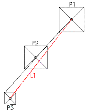
Illustration 4.
A single line (L1) indicates the
misalignment of the three pyramids, while a second line almost intersects three
corner locations, missing the northeast corner of P2 by several meters.
5. Linear alignment, including a
circular pyramid format.
Where we have failed is our assuming the
ancients not having gained advanced mathematical and geometric skills. However,
Egyptian sculptures and art forms were far advanced for this era in ancient
history, and sculpturing requires geometrical mathematics. We continue focusing
on the mathematical complexity utilized in their art form, yet we avoid the
mathematical implications within the pyramids.
These structures are square in shape, but
true geometry is not restricted to squares; it also implements triangles and
circles. By drawing the diagonal lines from each corner of the pyramids, their
centers are located. These diagonal lines represent triangles, while the
intersect location can be assigned as the center point for a circle inscribed
within the squares.
The south side of P1 was elected as the
reference line by choice, knowing that the ancients used the Sun for daily
measure of time and direction, and the Sun is circular.
By applying an inscribed circle to each
pyramid, a second attempt demonstrates a complete different set of linear
alignments (Ill. 5).
From illustration 4, it was demonstrated how
one line almost aligns with one corner from each pyramid; when the same line is
drawn tangent to the circle C3, it intersect the corners for the two large
pyramids perfectly.
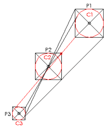
Illustration 5.
Inscribing circles within the squares, four
lines produce evidence of geometrical alignments between the three pyramids and
the tangents to the circles C1 and C3.
The entrances to the pyramid passages are
located on the lower north face of each structure, and their locations from
ground level vary considerably. Another oddity is their position being offset
from center; there are no coherent theories explaining why the ancients elected
to place the passages at various distances from the north-south axis. When
these locations are connected linearly, then we witness two additional
geometric correlations (Ill. 6).
Illustration 6.
Two geometric lines indicate the entrance
locations for the three pyramids.
6. Extended circular and triangular development, utilizing the complex.
In April 2000 AD, Mr. M. Kodera of Japan
introduced to the ARCE 2000 convention, a proposal, suggesting that the
complete Giza pyramid complex was mathematically pre-designed prior to
construction.
His means for demonstration included the
Sphinx and a “mirror” image of the lines drawn from the dimensioned pyramid
locations. The theory is most impressive, and the mathematical aspect
correlates within inches of Petrie’s true measures, but this minor error
instigated a closer review of his findings.
The following illustrates Mr. Kodera’s
proposal, including the Sphinx, boat pits, valley temples, and the main
causeway on site.
NOTE:
Precise dimensional locations for these additional structures were not
available at the time of this writing. From scaled drawings, produced by the
Survey of Egypt, they are positioned to the greatest possible accuracy (Ill.
7).
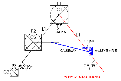
Illustration 7.
A “mirror” image triangle
formed using the south side of P1 representing Earth’s true east-west axis;
included are the Sphinx, valley temples, main causeway, and boat pits.
L1 was the original line introduced, and its
mirror image created to the east of the complex. It can be noted how L1
intersects the center portion of the Sphinx, then continuing through the
southern valley temple. It may also be noted how the main causeway ends
abruptly on the horizontal line drawn from P2.
Illustration 8 demonstrates other unique geometric formations
within this newly formed triangle.
Two vertical lines are drawn in the south
direction from P1 and P2 to the horizontal line formed by P3; their intersects
are marked as J1 and J2.
From J2, a circle is drawn having a radius
from J2 to the southeast corner of P2, and noted as C4. This circle intersects
the southern corners of P2 and both western corners of P3, a perfect
geometrical formation, using circular geometry (Illus. 8).
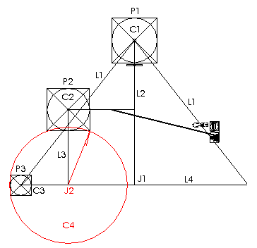
Illustration 8.
Circle C4 has a center location (J2) forming
a circumference intersecting the southern corners of P2 and the western corners
of P3.
Did the designers elect to utilize the
corner positions for these two pyramids to demonstrate their geometric
knowledge? This clearly indicates the
precise geometrical locations for P2 and P3, but an imagined triangle design
was required to reveal the center position for C4. This may provide an answer
to the possible reason why P3 was constructed offset from true north more than
the two larger pyramids; it actually prompts the inquisitive to investigate
various locations for measurement references.
In an attempt to confirm the designer’s
intentions, an additional circle is drawn from J1 to the southeast corner of
P1, and marked C5 (Illus. 9).
Now it is most evident that geometry was
implemented to position the three large pyramids on site. Circle C5 intersects
the southern corners of P1; similar to C4, it also passes the western corners
of P3. The designers duplicated this mathematical circular arrangement in their
original planning.
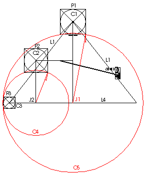
Illustration 9.
A second circle (C5) is drawn using J1 as
the center reference location, having a circumference intersecting the southern
corners of P1. This circle also cuts through the western corners of P3
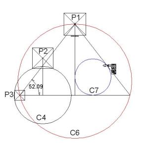
7. The third circle and the 2:1
ratio revealed.
Although C4 and C5 intersect the west side of
P3, there still remains a possible coincidence. However, one additional circle
is most obvious to construct, and we are guided to this circle by the extents
forming the “mirror” image triangle.
The original three circles (C1, C2 and C3)
were inscribed utilizing the square pyramid bases; now a third large circle
(C6) is drawn using the three point locations formed by L1 and the two
secondary lines L4 and L1 (Illus. 10).
The remarkable aspect to C6 is the size
ratio compared to C4; it is exactly twice the diameter of C4. These two circles
have a size ratio equal to 2:1, yet their center locations are completely
unrelated to each other (Chart 2).
From chart 2, an additional phenomenon is
recognized; the size ratio between C1 and C2, formed from the largest pyramids
on site, is identical to the ratio for the two large circles C5 and C6
respectively (1.07:1).
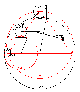
Illustration 10.
Using the three points formed by the
“mirror” image triangle, a third large circle is inscribed (C6). Comparing
circle C6 to circle C4 produces a 2:1 ratio.
|
|
|
C1 |
C2 |
C3 |
|
|
Measure |
9,070 |
8,477 |
4,158 |
|
C1 |
9,070 |
1 |
0.935 |
0.458 |
|
C2 |
8,477 |
1.070 |
1 |
0.491 |
|
C3 |
4,158 |
2.181 |
2.039 |
1 |
|
|
|
|
|
|
|
|
|
C5 |
C6 |
C4 |
|
|
Measure |
49918 |
46716 |
23432 |
|
C5 |
49,918 |
1 |
0.936 |
0.469 |
|
C6 |
46,716 |
1.069 |
1 |
0.502 |
|
C4 |
23,432 |
2.130 |
1.994 |
1 |
Chart 2.
The extrapolated dimensions are listed for
each circle, demonstrating the mathematical ratios between the three pyramid
circles: C1, C2 and C3. These ratios are then compared to the ratios for C4, C5
and C6.
To incorporate these circular elements, within
the Giza complex, required advanced knowledge in mathematical geometry.
However, without computer aided drafting programming, their designed measures
may have escaped detection indefinitely.
Before venturing further, we must consider
why the designers would chose a 2:1 ratio within the pyramid complex design.
Since three pyramids are constructed, then a 3:1 ratio would prove more
convincing.
It is obvious that the 2:1 ratio is being
presented to us, but only after discovering this circular geometry, and the
designer’s building several indicators to confirm their intent, as follows:
There are the two large pyramids compared to
one smaller pyramid, or simply stated, two pyramids verses one pyramid (2:1).
Introduced are the two boat pits and two valley temples. Although it is not
illustrated, there is a poorly constructed causeway leading from P3, in the
east direction, toward other smaller temples, therefore there are two
causeways.
The most well known demonstration for this
ratio is the King’s chamber within P1; its rectangular shape has sides
measuring 20 cubits by 10 cubits, a perfect 2:1 ratio. The designers are
indicating their primary objective being to emphasize the number two; it is
observed throughout the complete complex.
We are intelligent individuals; it is for us
to investigate deeper into the complex and discover the reason why.
8.
Relationship
to the Sphinx, valley temples, and boat pits.
a)
Sphinx and valley temples:
Below are the indicated locations for the
Sphinx and valley temples with relation to the line L1, formed by “mirror”
imaging (Illus.11).
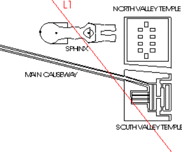
Illustration 11. The “mirror” image of L1 passes through the Sphinx and the
“south” valley temple.
From closer observation, three small circles
are positioned on the body of the Sphinx. These circles represent the locations
where deep and narrow holes are chiseled through the rock used in forming the
Sphinx’s torso. It may also be noted that the reason for these holes is
unknown, and continues to remain a mystery.
Construction of the “north” valley temple is
mainly comprised of limestone blocks; unfortunately this structure has
encountered severe damage by the natural elements and the forces of mankind.
Within this temple are ten rectangular settings, positioned in a geometrically
balanced rectangle formation.
The “south” valley temple is well preserved,
having exterior walls comprised of limestone blocks, while the interior
incorporates high quality granite, forming several complex and rectangular
shaped rooms.
The large room, on the west portion of this
temple, has two columnar rows, each spanned with individual lintels. Adjoining
is a central room having one row of columns, with several lintels remaining in
their original setting.
b)
Boat pits:
Two boat pits are situated adjacent to the
south wall of P1; they are no more than simple rectangular vaults constructed
below ground level; both contained the complete materials required to construct
a single boat. One pit had its contents removed, the boat reassembled and
presently displayed above the very location where discovered. Fortunately,
archeologist elected to reseal the second pit, entombing its contents
indefinitely (Illus. 12).
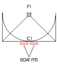
Illustration 12. Two rectangular holes were
cut into the limestone bedrock, on the southern side and adjacent to P1, each
containing a complete disassembled boat.
Although the concept of mirror-imaging the
initial triangle formation may appear “unprofessional” in mathematical
procedures, we must realize that the boat pits, valley temples and the Sphinx
are also constructed using mirror-image “artistic” designs. We may consider the
possibility that the designers intentionally incorporated these structures,
guiding us toward using mirror-image mathematics.
Continuing with Mr. Kodera’s theory, he
suggests that a circle (C7) inscribing the three sides of the secondary
triangle, independent of its center location, has a radius, measured
perpendicular to L1, pointing directly to the Sphinx (Ill. 13).
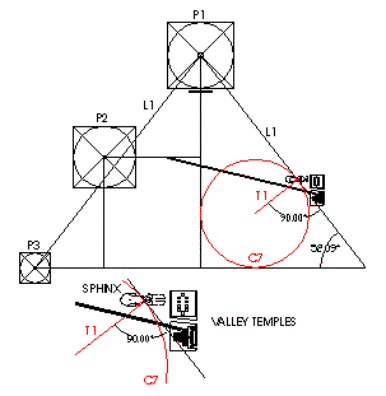
Illustration 13.
A three point geometric circle is inscribed
within the “mirror” image triangle, having a line (T1) drawn perpendicular to
L1 and pointing directly toward the head of the Sphinx.
From the above, we can safely confirm Mr.
Kondera’s proposal that the line, marked T1, when drawn from the center of C7
and perpendicular to line L1, points toward the Sphinx. The amazing feature is
the direction the line is drawn toward; it is directly in line with the hole
carved into the “head” portion of the Sphinx.
9. The “mirror”
image for the complete complex with Earth’s angular tilt and the number pi
revealed.
Three addition structures have been introduced,
showing or indicating mirror-image mathematics; what have not been analyzed are
the three pyramids themselves. The illustration below demonstrates the location
for P2 and P3 when their transferred image is included (Illus. 13).

Illustration 13.
Similar to line L1, the “mirror” image of P2
and P3 are transferred to the east side. The vertical line drawn from P2 passes
through the Sphinx and intersects L1 at the exact center of the sculpture.
The north-south axial line, drawn from P2,
cuts through the direct center portion of the Sphinx, remarkably, it also
intersects L1 at this very location. The probability for these two lines
intersecting at this location is extremely small. Combining this geometric
event with others previously introduced gives greater support to the concept
that the Giza site has been prepared using advanced mathematical knowledge.
Referring to the initial proposal that the
south side of P1 was prepared by aligned it east to west; the designers
actually confirm this in the complete format, by utilizing two of the newly
formed circles.
Illustration 14 demonstrates a line (L5)
drawn from the center location of C4, through the center of C6 and continuing
to the frontal section of the Sphinx. The remarkable aspect of this newly
formed line is the angular measure with reference to L4 (23.44 degrees); it is
equivalent to Earth’s angular tilt with respect to the Sun (23.433 degrees).
Illustration 14.
Line L5, drawn from C4 through C6, continues and intersects the
horizontal line of the Sphinx, located between the constructed “paws”. The
angle formed by L4 and L5 is 23.44 degrees, equal to Earth’s angular tilt
(23.433 degrees).
The above illustrations confirm why the
builders elected to construct the Sphinx where positioned; it confirms their
wanting us to expand the dimensions for the Giza complex using “mirror” image
mathematics.
The original line L1 is the single line used
by archeologists and Egyptologists to confirm that the three pyramids at Giza
are not geometrically aligned. However, it was illustrated how C4 intersects
the corner points of P2 and P3. This same circle is mathematically associated
with C6, resulting in a 2:1 ratio.
A circle drawn tangential to the three sides
of the formed triangle, created the smaller circle C7, from chart 4, these
three circular ratios are compared to each other.
|
|
|
C4 |
C6 |
C7 |
|
|
Measure |
23,457 |
46,716 |
14,868 |
|
C4 |
23,457 |
1 |
1.992 |
0.634 |
|
C6 |
46,716 |
0.502 |
1 |
0.318 |
|
C7 |
14,868 |
1.578 |
3.142 |
1 |
Chart 4.
The measures and ratios between the three circles C4, C6, and
C7
From Chart 4, the size ratio between for C6 and
C7 is 3.142:1, the exact numerical value for the number pi measured to three
decimal places. The angle measure between L1 and the east-west direction is
52.09 degrees. To draw two circles having a ratio of 3.142:1, and the smaller
circle positioned within a formed triangle as shown, the perfect measure must
have an angle equal to 52.10; no other angle will produce this ratio.
These three circles were specifically
designed within the Giza complex to indicate the builder(s) full knowledge of circular
measure.
The formula for calculating the
circumference of a circle is 2 times the number pi, and we are shown their
ingenious mathematical method used by incorporating the circular ratios of 2:1
and pi:1.
10. Conclusion.
Over two thousand five hundred years have
elapsed since the religious sector declared that all revolved around Earth. It
was a concept that created friction between the intellectual philosophers and
common man…. too difficult to understand, therefore impossible to perceive.
Are we continuing this identical ideology,
by applying mythical and legendary events to realistic and/or factual evidence.
Are we to continue displaying our arrogant attitude and supremacy in knowledge,
an attitude declaring that others before us could not have known what we are
learning today?
We have much to learn, and the above paper
is no more than the first and most basic step to unraveling the true reason why
the ancients constructed the Giza pyramids. The designers had a higher
intelligence level than we assume possible. For over four millennia they
successfully concealed this information from us, yet it remains openly a
daringly visible to all who visit.
Coincidences occur frequently, but not to
the extent as displayed from the above proposal. The Giza complex is a
mathematically designed array of stone monuments, and there are no intellectual
issues that can alter this simple fact.
The time has arrived; we must begin to open
our eyes, ears and mind; failure to do so will only prove our continuing
journey along the pathway of ignorance.
Petrie was not an Egyptologist when he first
visited Egypt, yet his systematic approach in archeology continues to this day.
Similar was Jean-Francois Champollion, the
first to decode ancient Egyptian hieroglyphs. He dedicated fourteen years of
his life, attempting to unlock the stories and historical events held within
the limited supply of ancient Egyptian papyrus script. Unfortunately, death
came immaturely for this young man, while witnessing his compiled notes and
findings being prepared for the first publication.
Jean-Francois was neither an archeologist
nor an Egyptologist; he was a Petrie, a Davidson, and a Lockyer. These
individuals did not go “against the grain” of Egyptology, they simply assisted
those who were confused or lost for reasoning.
We must ask ourselves…do we know the truth,
or are we lost for reasoning?
11) References.
Paper by M. Kodera, Comet Research Institute. Presented to the
51st annual meeting of the American Research Center in America (ARCE 2000).
The pyramids and Temples of Gizeh, W. M.
Flinders Petrie, 1883.
Discovering Ancient Egypt, R.F. MCKenty,
1997
General Map of the Giza Necropolis, Survey
of Egypt
The Pyramids of Egypt, I.E.S. Edwards, 1988
revised pbe.
“106” The Dawn of Man, C. Ross, 1999 pbe.
![]() To contact the author, e-mail Clive Ross: mailto:amitron2001@yahoo.com
To contact the author, e-mail Clive Ross: mailto:amitron2001@yahoo.com
____